Table of Contents
Cisco Packet Tracer
Packet Tracer by Cisco is a network simulator tool. You can create network topologies and test and experiment with them, and see behaviour such as what happens on routing protocols.
https://www.netacad.com/courses/packet-tracer
This page is for my own labs showing examples of various network concepts. Often seeing the examples and being able to experiment with the devices helps you to understand.
Updating devices to IOS 15 in Packet Tracer
Most switches and routers you drag onto your topology in Packet Tracer seem to be on older IOS 12.
There are some differences between older versions of IOS and IOS 15. One difference I am aware of is in IOS 15, output in show ip route will show Local Routes, which makes it easier to identify which interfaces have a particular IP address. Saves you having to look in running-config or somewhere else.
You can update routers and switches to run IOS 15:
https://www.reddit.com/r/ccna/comments/3dzto3/guide_to_using_ios_15_in_packet_tracer/
I made a lab with 2 topologies, 1 with the default routers dragged from the bottom toolbar with the IOS it comes with, and another after upgrading IOS via TFTP.
Note for the router there is not enough flash memory for the old IOS bin file so you must delete it first.
2960 switch
Old file: c2960-lanbase-mz.122-25.FX.bin,
New file: c2960-lanbasek9-mz.150-2.SE4.bin
2811 router,
Old file: c2800nm-advipservicesk9-mz.124-15.T1.bin,
New file: c2800nm-advipservicesk9-mz.151-4.M4.bin

2960_switch_2811_router_ios_upgrade.zip
Updating 2960 switch
- create topology with server (hosting TFTP server), configure server IP (e.g. 192.168.0.10)
- set up VLAN SVI interface and give it an IP address different to the server, but same subnet (e.g. 192.168.0.2)
- global config mode, go into VLAN SVI with command
interface vlan 1 - set IP address with command
ip address 192.168.0.2 255.255.255.0 - issue
no shutdownas the SVI will be shutdown by default
- check for connectivity (do some pings)
- copy file from TFTP server
- issue
copy tftp: flash:command. You'll be asked for TFTP server IP address, then the file you want to copy. You can just paste the filenamec2960-lanbasek9-mz.150-2.SE4.binwhen asked for it rather than type it. (you can also find that file name when viewing the server in the “Services” tab you can find the file you want and hit Ctrl+C) After file has completed copying, commandshow flash:will list the files in flash memory. Your copied file should show.
- issue boot system command to boot from new file, save config
- In global config mode, issue
boot system flash:c2960-lanbasek9-mz.150-2.SE4.bin - in enable mode issue
writeto save the new configuration.
- reboot
- issue
reloadcommand
- check new version
show version
Bundle and install mode:
https://www.lookingpoint.com/blog/ios-xe-catalyst-switches
https://content.cisco.com/chapter.sjs?uri=/searchable/chapter/c/en/us/td/docs/switches/lan/Denali_16-1/ConfigExamples_Technotes/Config_Examples/Misc/qos/m_install_vs_bundle.html.xml
Updating 2811 router
Updating this router is a little more tricky as this router doesn't have enough space on the flash memory to store the new IOS file, so you have to delete the existing IOS file first.
If somehow you mess this up, just delete the router in your topology and drag a new one on.
- create topology with server, give your server an IP address
- set up IPs on interface, give router's interface a different IP address on the same subnet to the server
- check for connectivity, do some pings
- delete old file from flash
- in global config, use
show flash:to list the files in flash memory - issue
delete flash:. You'll be prompted for the file you want to delete. You can copy/paste the file name you saw listed - issue another
show flash:to confirm the file has gone if you like
- copy new file from TFTP server
- in enable mode, issue
copy tftp: flash:. You'll be asked for the tftp server IP address and the file you want to copy. - Once file has copied you can issue
show flash:to confirm new file is there.
- issue boot system command to boot from new file, (delete any accidental tftp boot), save config
- issue
boot system flash:c2800nm-advipservicesk9-mz.151-4.M4.bin - somehow a
boot system tftpcommand may have found its way into the config (possible if you accidentally forgot to declare “flash” in the boot command). You will see this in running-config (show running-config), delete this with ano boot system tftpcommand - issue
writeto save config
- reboot
reload - check new version
show version
ARP
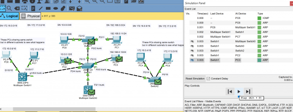
This lab demonstrates hosts on a network performing ARP lookups via broadcasts to discover IP addresses of other hosts.
(I also used this topology in one of the VLAN labs.)
One of the issues with this type of setup is that the ARP broadcasts go to ALL HOSTS. It literally goes everywhere. This is because by default a switch upon receiving a frame that has an unknown destination MAC address will forward it out of all ports except for the port it received it on.
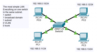
All hosts connected to a switch are in one broadcast domain.
To break up a big broadcast domain into smaller broadcast domains will require the use of VLANs.
Multiple PCs are linked together via switches.
4 subnets:
10.0.0.0/8
172.16.0.0/16
172.17.0.0/16
192.168.0.0/24
PCs on the same subnet can ping each other. PCs on different subnets cannot ping each other. To ping to hosts on different subnets it would require a router or a layer 3 switch setting up as a default gateway for the PCs. Note no VLANs are set up. ARP broadcasts will reach all PCs regardless of subnet.
For the PCs to show MAC address table from ARP lookups, arp -a,
clear ARP table arp -d
For the switches, to show the MAC address table from the ARP lookups, show mac address-table,
to clear table clear mac address-table.
Use Packet Tracer's simulation mode to slow the action and watch what happens to the ARP broadcasts.
Basic Routing
Basic Routing with Layer 3 switches
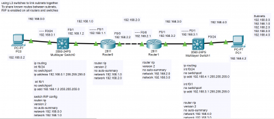
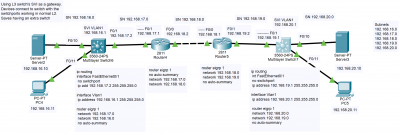
Simple labs to demonstrate use of Layer 3 switches. These can be more efficient than Layer 2 switches as some ethernet frames broadcasts flooding a broadcast domain are prevented. I used RIP and EIGRP in these labs so the devices will share routes between the subnets with each other. It was much easier than having to declare static routes.
Linking subnets together
Adding more devices

Using Layer 3 switch's Switch Virtual Interfaces (SVI) to act as a gateway
layer_3_switching_basic.zip
Loopback Interfaces
AD
FLoating static routes
RIP
RIP is apparently not going to be tested on the new CCNA exam so probably gonna skip this… Sorry!
EIGRP
EIGRP is apparently not on the new CCNA exam, so probably gonna skip this! Sorry.
OSPF
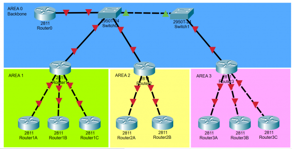
Not actually a working topology but something just to demonstrate what OSPF areas could look like.
Design borrowed from the Jeremy's IT Lab series of YouTube videos. Link
ospf_areas_topology_from_jeremys.zip
OSPF on Layer 3 switches?
OSPF DR/BDR Elections (buggy!)
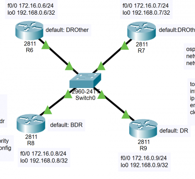
ospf_dr_bdr_elections.zip
This lab demonstrates the OSPF elections process in a network segment.
Packet Tracer itself appears to handle the OSPF DR/BDR elections incorrectly. (buggy!)
What should normally happen is a DR and BDR get elected automatically. Once the roles have been confirmed (the routers going through their neighbor states until they reach the full state), they would normally keep their roles. Only until the DR and BDR routers fail (or get restarted or lose their links) will a new election take place.
It is possible to influence the election to make a router the DR or BDR should you wish (for instance a more powerful router may be better at being the DR), but the DR and BDR must be taken down (either OSPF restarted or loss of link, shutdown interface etc) so this can force a new election.
Packet Tracer allows you to simply assign a higher OSPF priority to an interface, restart OSPF and it magically takes over the DR duties. This doesn't happen on real Cisco routers as the normal OSPF DR/BDR election rules apply.
- If the DR fails, the BDR becomes the new DR, then an election for the new BDR takes place
- When a “better router” enters the subnet (has higher OSPF priority or higher router ID), no preemption of the existing DR or BDR occurs (in other words the DR and BDR keep their roles until a new election has to take place)
Further reading - CCNA Official Cert Guide, Chapter 21 pg 504 “Configuring to influence the DR/BDR election”.
VLAN
This lab combines a few different topologies.
The most simple LAN.
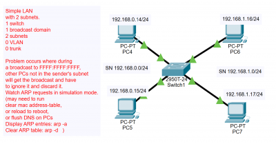
Simple LAN with 2 subnets. Note the hosts on differing subnets cannot communicate with each other, but being connected to the same switch means they are in the same broadcast domain.
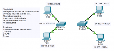
You can split the broadcast domain by installing an additional switch, but if you have many subnets you would need a switch per subnet.
You also have a problem if say the devices you want to split up conceptually in your network, but they are physically located in the same location. For example say 2 PCs are located on the same floor or room but people working on the PCs are of different departments, or one person on the floor is a supervisor/manager and needs access to different things to the other people. You may have to install extra switches just for the supervisors on that floor.
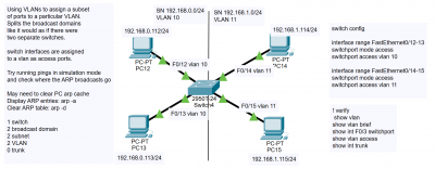
You can use VLANs to split the broadcast domains, even though the hosts are connected to the same physical switch. This makes collisions less likely and makes the network more efficient.
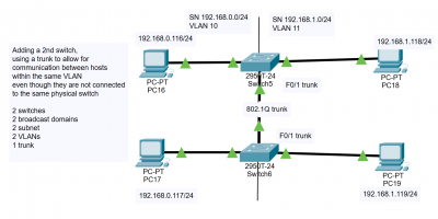
You can add an additional switch and configure it with VLANs, keeping the broadcast domains separated. A trunk is used to link the switches together.
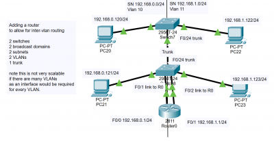
Adding a router allows you to do InterVLAN routing. This is the most simple way to do it by using a router's interfaces to allow the hosts on the different VLANs to communicate. However this is restricted by the number of interfaces you have on a router.
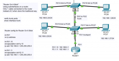
You can use Router On A Stick to save having to use multiple router interfaces. The router itself is linked to the switch with a trunk, then subinterfaces are set up on the router's interface. You can basically set up as many subinterfaces as you want.
Note the traffic between VLANs still has to physically traverse the ethernet cable itself, so it may be a consideration if you have a really long cable.
vlans_simple_intervlan_router_and_router_on_a_stick.zip
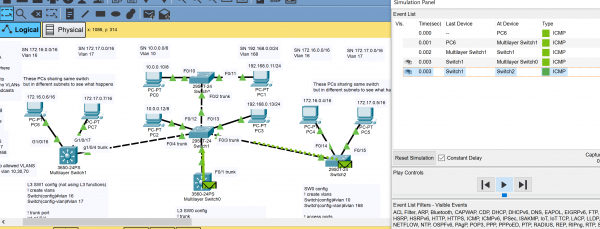
This lab demonstrates use of a Layer 3 switch for intervlan routing. No traditional router is required.
For the 4 VLANs, 4 SVIs (switched virtual interfaces) are set up on the L3 switch. IP routing must be enabled also with the ip routing command.
The screengrab shows the effect of broadcasts when VLANs are set up. Everything connected to the switch is no longer one big broadcast domain. Broadcast domains get split into smaller ones. Only switchports assigned to the same VLAN are in its respective broadcast domain. So broadcasts will only be forwarded to other ports either if its an access port for that VLAN or a trunk port that will allow that VLAN.
vlan_intervlan_routing_l3_switch_4_subnets_and_trunks.zip
VLAN DTP
VLAN VTP
VLAN - Native VLAN
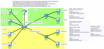
I had trouble figuring out what a Native VLAN was. My lab helps in explaining the concept as you can see how it can be used.
In principle a Native VLAN is an assigned VLAN number for anything that comes in untagged on a switchport.
The original idea for this was for ethernet hubs. Hubs are a legacy device, but for times when they were more common, they may have been needed to be connected to switches. Hubs by nature are a Layer 1 device. There's no concept of checking MAC addresses in a frame or anything like that. A hub will basically just repeat the signal it receives and copy it out onto all its other ports.
However if you are using VLANs on a switch and still have hubs connected, by the very nature of a hub there's no concept of a VLAN. This is where the NATIVE VLAN comes in. On the switchport you have connected to the hub you can assign a Native VLAN so the switch automatically associates traffic on that port to a particular VLAN. In other words any data reaching a switchport untagged will be associated with that VLAN.
By default any traffic coming in on a switchport would be associated with VLAN 1, but you can change this default native VLAN to something else. For security reasons it is best to change the default native VLAN from 1 to something else, some unused VLAN number.
hubs_and_bridge_native_vlan.zip
DHCP
HSRP
STP
Etherchannel
Switchport Security
ACL
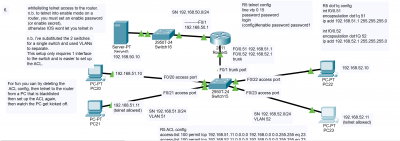
Various topologies showing permitting and denying various hosts. Topologies are all in one PT file.
Demonstrates standard ACLs and extended ACLs.
Permit 1 host, deny others

Deny 1 host, permit others
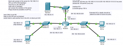
Permit telnet to a router on hosts, deny others.
acl_1.zip
NAT
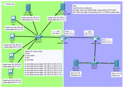
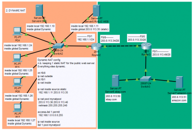
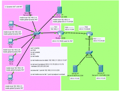
3 NAT topologies are here in the same PT file.
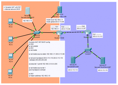
They demonstrate Static NAT, Dynamic NAT, Dynamic NAT with PAT, and Dynamic NAT with PAT and private addresses on the internal network assigned by DHCP.
nat_3_topologies.zip
Moved DHCP from a server to the router itself directly.
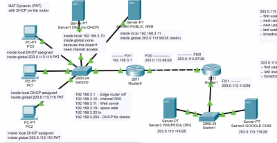
nat_dynamic_pat_dhcp_on_router.zip
IPv6
Cisco IOS Device Security
Console security
To set up a new router or switch you will need to console into the device with a rollover cable a computer.
A new router or switch will not have any security to protect its configuration.
They'll be no password required to access the device.
In most environments you will probably want to set a password to stop the casual user from going into the router and viewing or changing config.
Telnet and SSH access
When you get a brand new router or switch, you will need to console into the device with your laptop and a rollover cable to set it up. However long term you probably don't want to use the rollover cable all the time. You will want to set up remote access via Telnet and/or SSH. This means as long as you have IP access to the device, you can check and update configurations from a remote telnet/SSH terminal rather than having to be next to the device with your rollover cable.
AAA
NTP
Syslog
SNMP
QoS
Wireless
Packet Tracer Bugs
OSPF Costs reference-bandwidth changes
When working on OSPF, Packet Tracer appears to have trouble updating costs after updating the auto-cost reference-bandwidth values.
It seems to work if you do the changes immediately, but if you save the file, close and reopen, the costs seem to show as if it had the default reference-bandwidth of 100 Mbps.
A workaround I have found appears to temporarily correct the problem:
- enter Global Config (
configure terminal) - enter
router ospf 1(assuming you are sticking to using process ID 1 of course) - issue a different
auto-cost reference-bandwidth value, say 1000000 (million) - (you'll be warned that you should update reference-bandwidth on all routers)
- issue another auto-cost reference-bandwidth for the value you want, probably 100000 (hundred thousand)
- (you'll be warned again about updating all routers with the same reference bandwidth)
- issue
clear ip ospf processto reset OSPF (if still inside Global Config you may need to use thedooperator) - check your OSPF costs (
show ip route)
Note that if you save this topology into a file, then close Packet Tracer, then reopen the file, it appears the routers restart and are back to having the bug. You have to run the workaround again to reset everything to work as expected.
OSPF DR/BDR Elections
When you set up a network segment and have all routers' interfaces enabled for OSPF, DR and BDR elections should occur. Packet Tracer appears to break the normal rules of these elections by allowing you to simply assign higher priority to one interface, restart OSPF on that router, then it magically becomes the new DR. This should not happen on real Cisco routers as the DR/BDR elections should be non-preemptive, meaning the changes should not occur immediately and the routers keep their roles until something happens to those routers (e.g. interfaces go down).

